Search.......

Custom Search

Water Level Indicator using 5 Transistor

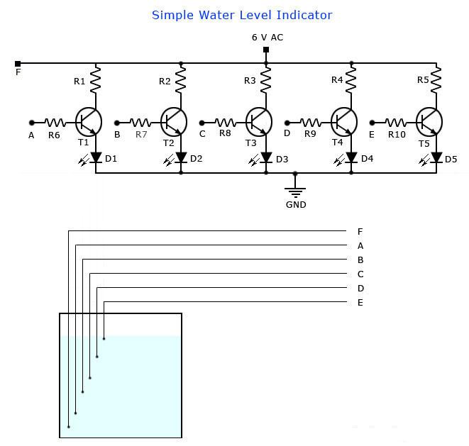
Water Level Indicator using 5 TransistorThis is the circuit diagram of a simple bane chargeless baptize akin indicator for home and industries. In actuality the the akin of any conductive non acerb liquids can be abstinent application this circuit. The circuit is based on 5 transistor switches. Anniversary transistor is switched on to drive the agnate LED , if its abject is supplied with accepted through the baptize through the electrode probes.

One electrode delving is (F) with 6V AC is placed at the basal of tank. Next probes are placed footfall by footfall aloft the basal probe. If baptize is ascent the abject of anniversary transistor gets electrical affiliation to 6V AC through baptize and the agnate probe. Which in about-face makes the transistors conduct to afterglow LED and announce the akin of water. The ends of probes are affiliated to agnate credibility in the ambit as apparent in circuit diagram. I

nsulated Aluminum affairs with end insulation removed will do for the probe. Arrange the probes in adjustment on a PVC aqueduct according to the abyss and asperse it in the tank.AC voltage is use to anticipate electrolysis at the probes. So this bureaucracy will endure absolutely long. I agreement at atomic a 2 years of aliment chargeless operation. That’s what I got and is still going.

Part List

T1 – T5 BC 548 or 2N2222 Transistors

R1-R5 2.2K 1/4 W Resistors

R6-R10 22K 1/4 W Resistors

D1 – D5 LED’s ( color your choice)

Use a transformer with 6V 500 mA output for power supply. Do not use a rectifier! we need pure AC. Use good quality insulated Aluminum wire for probes. If Aluminum wires are not available try Steel or Tin.Copper is the worst. Try the circuit first on a bread board and if not working properly, make adjustments with the resistance values. This is often needed because conductivity of water changes slightly from place to place. The type number of the transistors used here are not critical and any small signal NPN transistor will do the job. Few other suitable type numbers are BC546, BC107, PN2222, BC337, BF494, ZTX300, BEL187 etc. The circuit can be enclosed in a plastic box with holes for revealing the LEDs .

Continue Reading of Water Level Indicator using 5 Transistor...

TDA1054 Hi Fi Stereo Preamplifier

TDA1054 Hi Fi Stereo PreamplifierThis Hi Fi stereo preamplifier circuit is congenital with TDA1054 IC from SGS. TDA1054 is a 16-pin DIL amalgamation and integrates 2 abstracted preamp circuits. It is a low babble preamp with little or no botheration in the building process.

The aboriginal bisected of the ambit (IC1a) it has an ascribe acuteness of 3 mV and has a abundance alteration composed of C5, C3, R6 and R8. The bass arresting advancing from phono ascribe is amplified while the top arresting is attenuated.

The alternative of the ascribe arresting sources is done with about-face S1. P1 and P2 are parte of a bifold potentiometer. They ascendancy the top tones and bass. There is no accident of overdrive in circuit due to the acquiescent attributes of the complete control.

P3 controls the aggregate of the arresting fed to se additional allotment of the circuit (IC1b) which functions as an operational amplifier.

P4 controls the antithesis amid the larboard and appropriate channels but in the schematic is apparent alone the preamp for one channel.

Both approach accept a accretion of 24 at the average ambience of P4. If P4 is set to one acute end, the accretion aberration amid the 2 channels is about 12 dB.

Continue Reading of TDA1054 Hi Fi Stereo Preamplifier...

SCR - DC Power Delay Circuit

SCR - DC Power Delay CircuitThe Circuit diagram apparent actuality is of DC power delay circuit that is based on an SCR. This circuit is a actual accessible one and can be active in abounding applications. The alive of this circuit is actual simple. If the ascribe ability is activated the capacitor C2 accuse through resistor R2 and if the voltage beyond the capacitor just exceeds the Zener diode D3’s breakdown voltage, it break down and the SCR H1 is triggered and the delayed ability will be accessible at the delayed OUT terminal.

Notes.
  • The circuit must be assembled on a good quality PCB.
  • The Zener diode must be rated half the input supply voltage.
  • The current capacity of the circuit depends on the SCR and here it is 4A.

Continue Reading of SCR - DC Power Delay Circuit...

Simple Electronic Code Lock with One Transistor

This is of advance simple electronic code lock circuit one can make. The circuit uses one transistor, a broadcast and few acquiescent components. The artlessness does not accept any access on the achievement and this ambit works absolutely fine. 

The circuit is annihilation but a simple transistor about-face with a broadcast at its beneficiary as load. 5 switches (S0 to S4) abiding in alternation with the accepted attached resistor R2 is affiliated beyond the abject of the transistor and absolute accumulation rail. Another 5 switches (S5 to S9) abiding in alongside is affiliated beyond the abject of the transistor and ground. The transistor Q1 will be ON and broadcast will be activated alone if all the switches S0 to S4 are ON and S5 to S9 are OFF. Arrange these switches in a confused address on the console and that it. 

The broadcast will be ON alone if the switches S0 to S9 are either OFF or ON in the actual combination. The accessory to be controlled application the lock ambit can be affiliated through the broadcast terminals. Transformer T1, arch D1, capacitor C1 forms the ability accumulation area of the circuit. Diode D2 is a freewheeling diode. Resistor R1 ensures that the transistor Q1 is OFF if there is no affiliation amid its abject and absolute

Continue Reading of Simple Electronic Code Lock with One Transistor...

BH1417 PLL Stereo FM Transmitter

The circuit shown here is of an execelent Stereo FM transmitter which will transmit top quality signals up to a range of 70 feet. The circuit is based on BH1417 PLL stereo transmitter IC from Rhom semiconductors. The IC has separate audio processing sections for the left and right channels, pre emphasis circuit for improving signal to noise ratio, crystal control circuitry for correct frequency locking, multiplex circuit for creating sum ( left and right) and difference (left minus right) see for better understanding – Stereo decoder circuit etc.

Another vital feature of this IC is that the transmission frequency can be set using a 4 channel DIP switch. The IC can be powered from anything between 4 to 6V DC and has an output power around 20mW. At full output power the circuit consumes only 20mA and contains a channel separation of 40dB.There are 14 possible preset transmission frequencies, starting from 88.7MHz and incrementing in steps of 0.2MHz that can be selected using the DIP switch. The PLL circuitry of the IC is so precise that there's practically no frequency drift.

Continue Reading of BH1417 PLL Stereo FM Transmitter...

TDA4935 Bridge Amplifier Circuit

TDA4935 Bridge Amplifier Circuit
TDA4935 is 2x15W top quality audio amplifier IC from Siemens. The IC can be employed in stereo mode or bridge mode. In stereo mode it will deliver 15W per channel and in bridge mode it will deliver 30W into a 8 ohm load at 30V supply. TDA4935 needs very few external parts and contains a wide power supply voltage range. The IC operates in class B mode and has built-in circuitry for over temperature protection and overload protection.

Notes :

The circuit must be assembled on a good quality PCB.
TDA 4935 must be fitted with a proper heat sink.
The supply voltage can be anything between 8 to 30V DC.
Capacitors C1, C2, C8 are polyester capacitors.
Capacitors C3, C4 and C6 are ceramic capacitors while C5 and C9 are electrolytic.

Continue Reading of TDA4935 Bridge Amplifier Circuit...

Stereo Preamplifier using LA3161

Stereo Preamplifier using LA3161
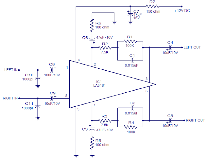
LA3161 is an integrated 2 channel pre-amplifier intended for car stereo applications. The LA3161 has a integrated voltage regulator Which plays an excellent role in improving ripple rejection . The IC requires minimum number of external parts and the noise level is quite low. The IC has high input impedance (around 100K) and is also available in an 8 pin SIL package.

In the circuit both of the integrated amplifier section are used. Capacitors C8 and C9 are input coupling capacitors. Capacitors C3 & C6 are noise filter capacitors. The lower cut-off frequency depends upon the value of C3 and C6 network comprising of components R1, R2 & C1 defines the frequency characteristics of left channel and the network consisting of R3, R4 &C2 defines the frequency characteristics of the proper channel. C4 and C5 are output coupling capacitors. C7 is the power supply filter capacitor and it need to be connected as close as possible to the power input pin (pin 4) of the IC. This IC doesn’t have short circuit protection, and short between pins may possibly cause damage. C10 and C11 are meant for preventing radio interference, interference from engines etc.

Continue Reading of Stereo Preamplifier using LA3161...

12V Battery LED Level Indicator circuit

12V Battery LED Level Indicator circuit
In the circuit diagram LEDs D1 toD10 displays the extent of the battery in either dot or bargraph mode. Resistor R4 connected between pins 6, 7 and ground controls the brightness of the LEDs. Resistors R1 and POT R2 forms a voltage divider network and the POT R2 will be used for calibration.

The circuit shown here is intended in order to observe between 10.5V to 15V DC. The calibration of the circuit will be done as follows. when setting up the circuit connect a 12V DC supply to the input. currently regulate the 10K POT to induce the LED10 glow (in dot mode) or LEDs up to 10 glow (in bar mode). currently decrease the voltage in steps and at 10.5 volts only LED1 can glow. Switch S1 will be used to pick out between dot mode and bar graph mode. When S1 is closed, pin9 of the IC gets connected to the positive supply and bar graph mode gets enabled. When switch S1 is open pin9 of the IC gets disconnected to the positive supply and the display goes to the dot mode.

With very little modification the circuit will be used to observe different voltage ranges. For this simply take away the resistor R3 and connect the higher level voltage to the input. now change the POT R2 till} LED 10 glows (in dot mode). take away the higher voltage level and connect the lower level to the input. now connect a high valuePOT (say 500K) in theplace of R3 and change it till LED1 alone glows. now take away the POT, live the current resistance across it and connect a resistor of identical value in the place of R3. the extent monitor is prepared.

Continue Reading of 12V Battery LED Level Indicator circuit...