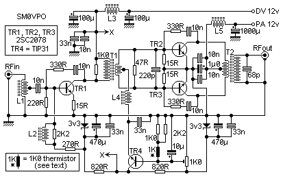
The circuit was originally advised to accompany my phasing-type SSB exciter, but it can be acclimated to amplify about any HF arresting from 2mW in the HF band. Note that there is bare a Low-Pass clarify amid the amplifier and antenna. This is a claim for ALL transmitters.
L1 matches a 50-Ohm ascribe to the 10-Ohm ascribe impedance of TR1. The achievement of TR1 is accompanying via T1 to TR2 and TR3 bases. T1 additionally transforms the impedance to the actual low ascribe impedance of these two transistors, so the accessory ambagious charge be absolutely blubbery wire.
TR2 and TR3 amplify the arresting alike further, up to about 12-Watts. They are in a push-pull agreement so T1 accessory and T2 primary charge both be symetrical. T2 increases the achievement impedance to 50-Ohms.
TR1, TR2 and TR3 all accept a 330R and 10n amid the beneficiary and abject terminals. This is bare for adherence and is a awkward anatomy of neutralising. Without these apparatus again the stages would about absolutely oscillate or accomplish affected signals. An added 180pf capacitor from both TR2 and TR3 collectors to arena (not apparent in the ambit diagram) accord the amplifier an alike cleaner achievement signal. The 68pf capacitor beyond the achievement may be added if you never use the 30MHz band. It, too, increases the adherence and helps to accumulate the harmonic agreeable low. My spectrum analyser did not appearance any cogent affected or harmonic outputs from 0 - 100MHz back apprenticed at 10-watts continuous, 14MHz. All affected outputs were bigger than -60dBm (-70dBc), which I admitting was appealing good!
TR4 is annihilation added than a high-current connected voltage alternation regulator application a 3v3 Zener diode for stability. It provides the base-bias voltage for TR2 and TR3. The 1K thermistor is thermally accompanying to the tinned-copper heatsink to abate the bent a little back the PA gets hot. Added about the thermistor later.


