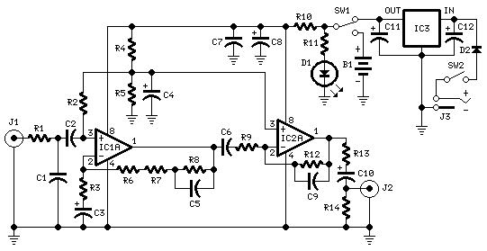
This assemblage was advised for amateurs owning an old accumulating of vinyl recordings and absent to accept it digitally remastered into a claimed computer.
Or sometimes they would accept to an old, invaluable, LP accumulating through their avant-garde Aerial Fidelity chain, usually defective a phono preamp stage: this is a ambit able of acceptable their needs.
The assemblage is powered by a 9V battery, acceptance a quick and accessible affiliation to all high-level ascribe preamplifier stages and the actual low accepted cartoon of the ambit will agreement a continued array life.
Despite the low voltage supply, ambit achievement with affective allurement pick-ups is absolutely good, featuring aerial ascribe afflict capability, actual low baloney and authentic reproduction of the RIAA equalization curve, acknowledgment to a two-stage op-amp chip in which the RIAA equalization arrangement was breach in two halves: an ascribe date implementing the bass-boost allotment of the RIAA equalization ambit active in a alternation acknowledgment agreement and a added stage, implementing the treble-cut allotment of the ambit by agency of a added op-amp active in the blow acknowledgment configuration.
Battery operation additionally minimizes the achievability of hum pick-up, a abeyant crisis consistently present in aerial gain, aerial acuteness phono preamps.
As the absolute accepted cartoon of the ambit is about 1.2mA back powered by a 9V battery, the use of a pilot lamp LED will be the above account of accepted consumption. Therefore, a actual small, low accepted red LED is recommended for this purpose. Using a 6.8K attached resistor as defined for R11, the LED will draw an added accepted of 1mA: it will not flash brightly, but can be still calmly seen.
A typical, carbon-zinc, 9V array will acquiesce the ambit to accomplish for about 180 hours, admitting an acrid array will aftermost for added than 250 hours. If the LED is omitted, durations will be about doubled.
In any case, for those whishing to additional the battery, the ambit can additionally be powered by a accepted alien ability accumulation adaptor, rated at about 12-15V dc, 10mA or higher. In this case, the ambit ascribe afflict adequacy will access further.
Notes:
- The circuit board should be preferably enclosed into a small metal case.
- The circuit diagram shows the Left channel only and the power supply.
- Some parts are in common to both channels and must not be doubled. These parts are: R4, R5, R10 and R11, C4, C7, C8, C11 and C12, D1, D2, IC3, SW1, SW2, J3 and B1.
- IC1 and IC2 are dual Op-Amps, therefore the second half of these devices will be used for the Right channel.
- If you intend to use exclusively the battery supply, IC3, D2, C11, C12, SW2 and J3 must be omitted and SW1 can be substituted by a SPST Toggle or Slide Switch.
- Wanting to power the circuit by the mains only, omit B1 and SW1, then hard-wire the junction of R10 and R11 to the output pin of IC3.
- Pilot lamp D1 and its current limiting resistor R11 are optional.
- Please note that the circuit requires about 15 seconds to become fully operative after power-on.
R1,R3____________2K2 1/4W Resistors
R2,R4,R5_______100K  1/4W Resistors
R6______________39K  1/4W Resistor
R7_______________3K9 1/4W Resistor
R8_____________390K  1/4W Resistor
R9______________33K  1/4W Resistor
R10,R13________220R  1/4W Resistors
R11______________6K8 1/4W Resistor (Optional, see text)
R12_____________75K  1/4W Resistor (or two 150K resistors wired in parallel)
R14_____________10K  1/4W Resistor

C1_____________100pF  63V Polystyrene or Ceramic Capacitor
C2,C6____________1µF  63V Polyester Capacitors
C3,C4___________47µF  25V Electrolytic Capacitors
C5______________10nF  63V Polyester Capacitor 5% tolerance or better
C7_____________100nF  63V Polyester Capacitor
C8_____________100µF  25V Electrolytic Capacitor
C9_______________1nF  63V Polyester Capacitor 5% tolerance or better
C10______________4µ7  25V Electrolytic Capacitor
C11____________220µF  25V Electrolytic Capacitor
C12___________1000µF  25V Electrolytic Capacitor

IC1__________LS4558   Dual High Performance Op-Amp
IC2___________TL062   Dual BIFET Op-Amp
IC3___________78L15   15V 100mA Regulator IC

D1______________LED  small dimensions, low current (Optional, see text)
D2___________1N4002  200V 1A Diode

SW1____________SPDT  Toggle or Slide Switch
SW2____________SPST  Toggle or Slide Switch

J1,J2___________RCA audio input sockets
J3______________Mini DC Power Socket

B1_______________9V  PP3 Battery

Clip for PP3 Battery


