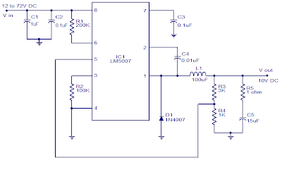
The circuit diagram shown here is a 10V Switching regulator based on the National Semiconductor LM5007. The LM5007 is a step composed of the switching regulator that has all the systems necessary for making a circuit switching regulator's cost effective and reliable. The IC is available in MSOP-8, LLP-8 packages and has lots of features like thermal locked output voltage, duty cycle limitation, current limit etc.
The output voltage of this regulator can be adjusted with resistor R3 and R4. For given values of R3 and R4 in the circuit, the output voltage is 10V. The equation governing the output voltage Vout = 2.5 x (R3 + R4) / R4. Resistor R1 sets the time switch and C4 is the drive boot strap capacitor. Resistance R2 determines the variation of free time and C3 is a decoupling capacitor.


