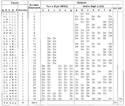
 For example, if the input PA, PB, PC, PD, PE = 11 01 0, then after the translated by the decoder will produce numbers a, b, c, d, e, f, g (MSD) = ten 0 one One one One as well as a, b, c, d, e, f, g (LSB) = 0 0 one 0 0 one 0. These numbers indicate that the negative pole (cathode) of the LED in a specific segment of a low voltage bias (0) so that the lights forming the number "12" on the seven-segment display devices. For more details can be seen in the picture.
This decoder circuit also serves to modify the 5-bit binary numbers to decimal to be displayed by seven segments. This decoder has a five pin input PA, PB, PC, PD PE & 14 pin output marked a, b, c, d, e, f & g.

In the circuit above using Seven Segment (7 Segment ) commond anode type. The principle works is, if the input pin Seven Segment a, b, c, d, e, f, g given voltage 0 volts, the LED on the Seven Segment props will be forward biased & turned to form a specific figure.
The seven segments may even be supplied with higher voltage (up to 18 V) but you need to replace the R 22 ohm with a greater value; morever, an appropriate mast Rext be Chosen.

Absolute maximum rating IC TDA4092
- Supply voltage…………….... 10 V
- Input voltage……………….. .10 V
- Off state output voltage…...... 20 V
- Output current………………. 22 V
- Total power dissipation ….. ... 0.8 mW
- Storage and junction storage… -25 to 150 C
- Operating temperature………. 0 to 70 C


